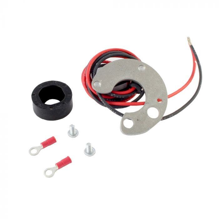
Fitting Instructions - RR182 Delco Remy Distributor Ignitor
Fitting Instructions - RR182 Delco Remy 8 Cylinder Distributor Ignitor
Before installing, please read the following important information.
- The Ignitor is designed to be used in 12-volt negative ground systems.
- The Ignitor is compatible only with a "points style" coil. Eight cylinder engines require a minimum of 1.5 ohms of resistance.
- Never use a High Energy Ignition type coil with the Ignitor. This type of coil generally used with factory fitted Electronic Ignition Systems will damage the module, cause it to fail, and void the warranty. Use the original coil.
- A new coil is recommended as this Ignitor depends on a good coil.
- The red wire from the Ignitor must be connected to the positive (+) side of the coil, or a 12 volt switching power source. The black wire must be connected to the negative (-) side of the coil. (See Figure 2)
- The magnet sleeve has green tape attached to it. DO NOT REMOVE THIS TAPE.
PRIOR TO INSTALLATION TURN THE IGNITION SWITCH OFF OR DISCONNECT THE BATTERY.
- Remove the distributor cap and rotor. Do not disconnect spark plug wires from cap. Examine cap and rotor for wear or damage. Replace if necessary.
- Disconnect the points wire from the negative (-) side of the coil.
- Remove the points, condenser, grommet with the ignition wire and points attachment plate. It is not necessary to remove the distributor cap clips.
- The Ignitor does not require any modification to the distributor body. Therefore the points, condenser, and hardware can be saved so they can be used as backup.
- Clean any oil or dirt from the breaker plate and cam.
- Insert the Ignitor black and red wires through the distributor housing verifying the black rubber grommet is seated properly.
- Install the Ignitor module using the provided hardware in the same manner as a set of points. The Ignitor plate fits easily and firmly. No drilling, cutting, or extra hardware is required. When the correct kit is installed modifications are not needed. The plate has 3 large holes around its periphery. The smaller centre hole fits over the remaining points post allowing the 2 outer holes fit over the remaining adjusting screws. The small screw provided with the kit is used to secure the Ignitor plate to the base plate. Before tightening this screw ensure that the old adjusting screws are turned to such a position to allow the Ignitor plate to fit centrally round the rotor post and that it fits flatly onto the base plate. Then tighten the screw.
- If the distributor ground wire was removed during the installation process be sure it is re-attached securely.
- Place the magnet sleeve down onto the distributor shaft. Rotate the sleeve until you feel the cam line up correctly. Push down firmly until seated.
- The air gap between the Ignitor and magnet sleeve is fixed and pre-set so needs no further adjustment. There should be an air gap of over 0.30".
- Replace rotor and distributor cap. All spark plug wires should be seated securely.
- Connect the Ignitor black wire to the negative (-) side of the ignition coil.
- Connect the Ignitor red wire to the ignition switch side of the resistor. (See Figure 2).
- Reconnect battery and make sure all wires are connected.
- The engine can now be started. Let the engine run a few minutes and then set the timing in the conventional manner.
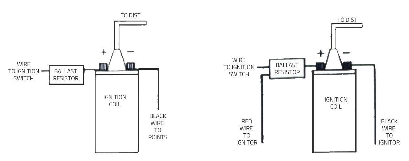
Figure 1 - Wiring Diagram - Conventional Points System with Ballast Resistor
Figure 2 - Wiring Diagram - Ignitor System with Ballast Resistor
Ignitor Common Questions & Answers
Q: What is the first thing I should check if the engine would not start?
A: Make certain all wires are connected securely to the proper terminals.
Q: The engine still will not start or runs unevenly. Are there any tests I can do?
A: Yes, remove the red Ignitor wire from the coil, Connect a jumper wire from the positive side of the battery to the red Ignitor wire just removed from the coil. If the engine starts you have a low voltage problem (This is a very common problem). Remember this is just a test. It is not intended for permanent installation.
Q: How can I fix a low voltage problem?
A: First, if you have an external ballast resistor, connect the red Ignitor wire to the ignition wire prior to the ballast resistor. Secondly, if you do not have a ballast resistor you must connect the red lgnitor wire to a 12-volt source that is controlled by the ignition switch.
Q: What type of a coil do I need?
A: The Ignitor is compatible only with a "points style" coil. Six & eight cylinder engines require a minimum of 1.5 ohms of resistance.
Q: How do I check my coil for resistance?
A: First you need an ohmmeter. Remove all the wires from the coil. Attach the meter to both the positive and negative terminals. The reading must be 1.5 ohms or greater for six & eight cylinder engines, and 3.0 ohms or greater for four cylinder engines. (Your local auto parts store can do this for you if you do not have an ohmmeter).
Q: What do I do if my coil does not have enough resistance?
A: You may purchase and install a ballast resistor from your local auto parts store. You may also choose to purchase a Flame-Thrower 40,000-volt coil, which provides resistance internally. Note: Many vehicles come with a resistor wire or a ballast resistor. These applications do not need an additional resistor.
Q: What happens if I leave the ignition switch on when the engine is not running?
A: This can cause your coil to overheat, which may cause permanent damage to the coil and the Ignitor.
Q: May I modify the length of the Ignitor wires?
A: Yes, you may cut the wires to any length your application may require. You may also add lengths of wire if needed (20-gauge wire). Please make sure all wire splices are clean and connections are secure.
RR182 Delco Remy Distributor Ignitor
This kit replaces the twin contact points in the distributor with an electronic module.
Contact breakers can become inefficient when wear in the distributor causes the shaft to oscillate, preventing a stable gap between the contacts. This causes an uneven spark between cylinders, resulting in 'lumpy' engine running and poorer fuel economy. Electronic ignition is not affected by this, ensuring smoother running and enhanced economy.
The kit is fully contained underneath the distributor cap, so the modification is unnoticeable.
This Prestige Parts® product is sold with a 3 year warranty.