Fitting Instructions - RR181 Ignitor for Lucas 20 D8 Distributor
Fitting Instructions - RR181 Ignitor for Lucas 20 D8 Distributor
Before installing, please read the following important information.
1. The Ignitor is designed to be used in 12-volt negative ground systems, with or without a ballast resistor.
2. The Ignitor is compatible only with a "points style" coil. Eight cylinder engines require a minimum of 1.5 ohms of resistance.
3. Never use a High Energy Ignition type coil with the Ignitor. This type of coil generally used with factory fitted Electronic Ignition Systems will damage the module, cause it to fail, and void the warranty. Use the original coil.
4. A new coil is recommended as this Ignitor depends on a good coil. A new coil is recommended as this Ignitor depends on a good coil.
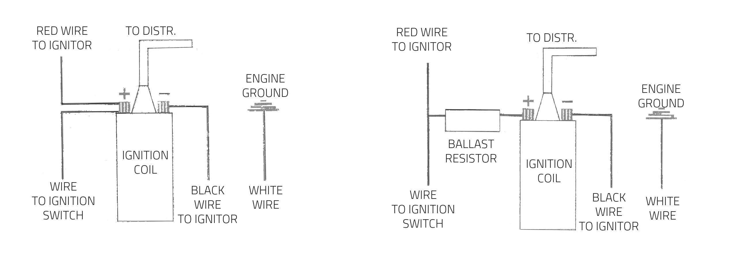
5. The red wire from the Ignitor must be connected to the positive (+) side of the coil. The black wire must be connected to the negative (-) side of the coil. (See Figure 2
6. Some magnet sleeves may have green tape, DO NOT REMOVE IT.
PRIOR TO INSTALLATION TURN THE IGNITION SWITCH OFF OR DISCONNECT THE BATTERY.
1. Remove the distributor cap and rotor. Do not disconnect spark plug wires from cap. Examine cap and rotor for wear or damage. Replace as needed.
2. Disconnect the points wire from the negative (-) side of the coil.
3. Remove the points, condenser, and grommet.
4. The Ignitor does not require any modification to the distributor. Therefore the points, condenser, and hardware can be used as backup.
5. Clean any oil or dirt from the breaker plate and cam.
6. Insert the Ignitor black and red wires through the side of the distributor housing verifying the rubber grommet is seated properly. The exterior of the grommet should fit flush with the outside of the housing.
7. Install the Ignitor module using the provided hardware in the same manner as a set of points. NOTE: The point’s adjustment screw hole is used as a pilot for the Ignitor locating pin. Confirm the mounting plate is flat and fits without any drilling, cutting, or extra hardware. Modifications to the kit are not needed.
8. If the distributor ground wire was removed during the installation process be sure it is re-attached securely.
9. Place the magnet sleeve down onto the distributor shaft. Rotate the sleeve until you feel the cam line up correctly. Push down firmly until seated.
10. Set the air gap between the module and magnet sleeve using the provided plastic feeler gauge (0.030" thick). This is done in the same manner as points. Note: In some kits the modules are stationary and do not require air gapping.
11. Replace rotor and distributor cap. All spark plug wires should be seated securely.
12. Connect the Ignitor black wire to the negative (-) side of the ignition coil.
13. Connect the Ignitor red wire to the ignition switch side of the coil. (See Figure 2).
14. Reconnect battery and make sure all wires are connected.
15. The engine can now be started. Let the engine run a few minutes and then set the timing in the conventional manner.
FIGURE 1 Wiring Diagram - Ignitor System without Ballast Resistor
FIGURE 2 Wiring Diagram - Ignitor System with Ballast Resistor
Ignitor Common Questions & Answers
Q: What is the first thing I should check if the engine would not start?
A: Make certain all wires are connected securely to the proper terminals.
Q: The engine still will not start or runs rough. Are there any tests I can do?
A: Yes, remove the red Ignitor wire from the coil, Connect a jumper wire from the positive side of the battery to the red Ignitor wire just removed from the coil. If the engine starts you have a low voltage problem (This is a very common problem). Remember this is just a test. Not intended for permanent installation.
Q: How can I fix a low voltage problem?
A: First, if you have an external ballast resistor, connect the red Ignitor wire to the ignition wire prior to the ballast resistor. Secondly, if you do not have a ballast resistor you must connect the red ignitor wire to a 12-volt source that is controlled by the ignition switch.
Q: What type of a coil do I need?
A: The Ignitor is compatible only with a "points style" coil. Six & eight cylinder engines require a minimum of 1.5 ohms of resistance. Four cylinder engines require a minimum of 3.0 ohms of resistance.
Q: How do I check my coil for resistance?
A: First you need an ohmmeter. Remove all the wires from the coil. Attach the meter to both the positive and negative terminals. The reading must be 1.5 ohms or greater for eight cylinder engines.
Q: What happens if I leave the ignition switch on when the engine is not running?
A: This can cause your coil to overheat, which may cause permanent damage to the coil and the ignitor