Fitting Instructions & Warranty Guidelines - Air Conditioning Compressor UE43934.02
Fitting Instructions & Warranty Guidelines - Air Conditioning Compressor UE43934.02
S6 Compressor Oil & Refrigerant Capacities
The S6 compressor is an innovative replacement for the Harrison A6, in this case supplied with a special clutch and pulley arrangement for Rolls-Royce and Bentley applications. With its new design it will require a different type and volume of oil than the original A6, and a different amount of R134A refrigerant gas.
Each S6 compressor contains 300cc (10.14oz) of PAG 46 oil. Additional oil may be required to achieve the correct ratio of oil needed in a specific system which is 17 to 20 percent oil to refrigerant (ex. 52oz. refrigerant x 17% = 8.84oz total). Please note: in this example the installer would be required to remove 1.3oz of PAG 46 to reach the total volume.
We recommend installing 800g (28.2oz) of R134A refrigerant for standard cars (i.e., cars without a separate rear air conditioning system in the rear of the car). Should you experience any noise from the system you may remove some refrigerant until the air conditioning system becomes quiet.
Handy Hint: Before you fill the compressor, drain any residual oil from it into a clean container and add oil as necessary before refilling to obtain the correct volume.
Instructions & important Warranty Conditions
The following installation requirements must be performed to be considered for warranty:
- Filter drier or accumulator drier must be replaced or overhauled with the appropriate desiccant bag kit.
- Orifice tube or liquid line that contains fixed orifice tube must be replaced (if applicable)
- Expansion valve must be replaced.
- Correct type and amount of refrigerant oil must be used (as above).
- The A/C system must be thoroughly cleaned with an approved flush, using an approved method.
- The entire A/C system must be evacuated for a minimum of 45 minutes.
- Only R-134a refrigerant may be used.
- Installation must be performed by a certified professional repair technician.
This warranty does not cover defects or malfunctions which result from causes beyond our control, including, without limitation:
- Alteration outside of manufacturer’s factory in any way that negatively affects the integrity of the compressor.
- Misuse, abuse, accident, neglect or other abnormal use.
- Damage due to refrigerants, chemicals, or other agents due to improper installation.
- Ingress of dirt or foreign matter into the air conditioning system
Thermal Limiter Conversion Instructions
When replacing the original GM A6 compressor with UE43934.01-X or UE43934.02-X compressor it may be necessary to bypass the thermal limiter fuse arrangement, as the replacement unit operates with a pressure switch (included with the compressor) rather than a superheat switch. Both pressure switches and superheat switches with a thermal limiter fuse are fitted to protect the system.
Early model GM vehicles through 1987 originally used a superheat switch along with a thermal-limiter fuse for a system protection device, although some cars were converted to a pressure switch when replacement A6 compressors were supplied with these switches from Rolls-Royce Motorcars Limited. For a variety of reasons, it has become desirable to convert any superheat switch arrangement to a pressure switch setup. The superheat switch (CD5998) is a normally open switch that closes to ground with high temperature or pressure. This causes the heater to burn the fuse and opens the clutch circuit.
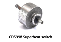
CD5998 is used with those versions of the original A6 compressor (UE43934) with the configuration below.

The high pressure (JLM165-X) switch or switch kit (MC1315-X + PT1032-X) is normally closed to ground to complete the clutch circuit and opens with high pressure to shut off the clutch circuit. JLM165-X or MC1315- X/PT032-X are used with replacement compressor UE43934NF.01-X & UE43934.02-X.
Once the pressure switch is in place in the compressor, a minor wiring change is necessary as described below.
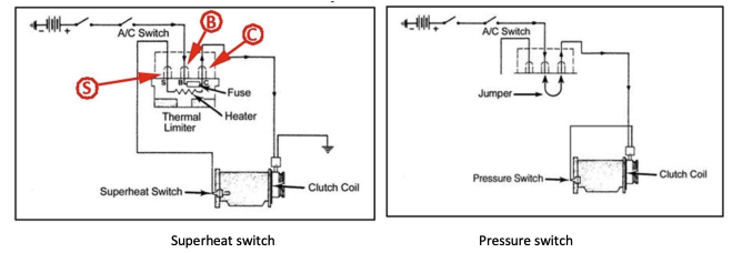
Dispose of the thermal limiter fuse. Connect a jumper lead between terminals “B” & “C”. Terminal “S” is not used. Take the clutch wire that was connected to earth/ground and connect it to the superheat switch.