Valve Stem Seal Upgrade - UE7428NF and EB1886NF
Valve Stem Seal Upgrade: Part Number Reference UE7428NF & EB1886NF
Crewe cars from 1946 onwards often suffer oil consumption at a far higher rate than desired. Although oil consumption is mainly a concern rather than a problem, it is useful to note that there is a simple invisible modification, which not only reduces oil consumption markedly, but also prolongs valve stem life and reduces coking. Furthermore, the oil stays cleaner between changes.
For the 6 cylinder and V8s alike, the improvement is most satisfying in every case.
The solution is to fit modern valve stem seals in place of the original waxed asbestos rope grommet type. The modern type of control seal limits the oil to the stems, but also make sure it stays there and is not sucked or blown out thereby improving valve stem lubrication.
The control seals here are a no-compromise product using Viton as the noble material. The sealing lip is spring loaded to compensate for any valve stem or seal wear over very long periods. They have been selected for their highest quality, extremely long life and ideal valve stem protection. On all post-war cars, they may be fitted without removing the cylinder heads. The 6-Cylinder seals have been fitted in the same manner to pre-war cars with equal success. No special tooling or machining is necessary, but the use of a suitable valve compressor or lever will be required to compress the valve springs. A simple lever may be made easily from a piece of flat steel (Fig.3).
V8 Motors (Product UE7428NF)
There is a Rolls-Royce product support leaflet covering all cars from the S2-SC2 and Phantom V cars onwards using Crewe part number UE75351 as introduced in production during the 1980s. The seals offered by Introcar are similar in design but utilise superior materials.
Removal of the valve springs in-situ is covered in TSD5000 Chapter. E8 as follows:
1. Remove all spark plugs and block the holes with tissue paper
2. Remove the rocker covers and the rocker gear. Plug all the oil holes and pushrod holes with tissue paper
3. Turn the crankshaft so that the cylinder to be worked upon is exactly at top dead centre. This prevents the valves from dropping more than a few millimetres once the valve springs are removed 4. Using the spring compression device (Fig. 3), compress the spring and remove the valve collets. Release the compression device and remove the valve spring.
Applicable only to cars before Silver Spirit chassis 6750:
5. Remove and discard the Gland spring, Valve grommet housings and the original valve stem seal (valve grommet).
6. Inspect the sharp edge at the top of the valve guide. If it is razor sharp, it is advisable to flatten to top of the guide a little, best done with a miniature grinding wheel with a bore of at least 3/8” to slide down the valve stem. By hand, rotate the grinder until the guide head is blunt.
Applicable to all cars:
7. Polish the outer face of the guide with 320 grit sandpaper and clean away all debris
8. Coat the outside of the guide with light grade petroleum jelly. Grit-free hand cleaner is an ideal lubricant
9. Fit the new valve stem seals. These should be fitted using an appropriate drift to ensure a square fit on the valve guide. A suitable drift is a used gudgeon pin or a long-reach 14mm (9/16”) socket (Fig. 1)
10. Fill the valve spring cap centre hole with a high-temperature Silicone Gasket RTV and also liberally apply some to the cotters
11. Fit the valve spring and its top washer, and compress the valve spring to fit the collets. Once the spring is released, ensure that the RTV gives a good seal between the valve stem and the spring cap, and remove excess RTV
12. Reassemble the valve train once all valves have been completed.
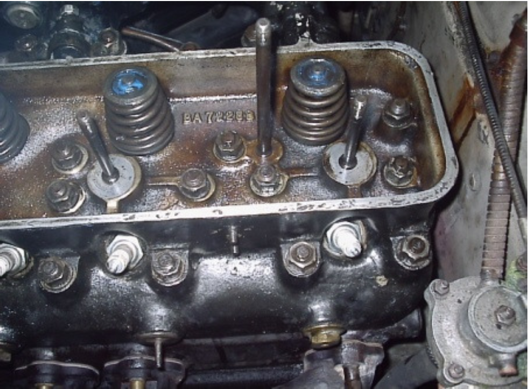
Figure 2
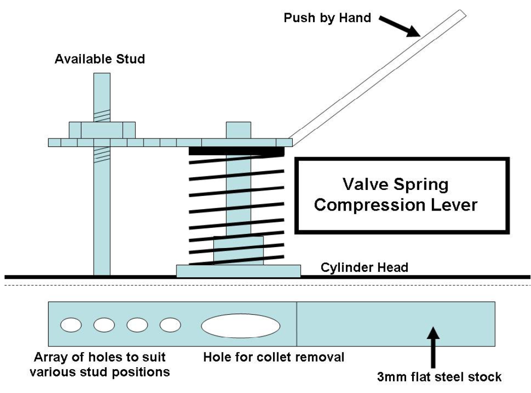
Figure 3
6-Cylinder Postwar Motors (Product EB1886NF)
Upgraded seals may readily be fitted to the inlet valve guides of all these cars. Introcar offers a kit to achieve this end. The procedure is broadly the same as for the V8 motors. As the inner valve spring acts as a gland spring, the domed grommet housing must be replaced by the flat washer of a very slightly greater thickness as provided in the Introcar kit for these cars.
Removal of the valve springs in-situ is covered in the workshop manuals as follows:
1. Remove all spark plugs and block the holes with tissue paper
2. Remove the rocker covers and the rocker gear. Plug all the oil holes and pushrod holes with tissue paper
3. Turn the crankshaft so that the cylinder to be worked upon is somewhat below top dead centre.
4. Insert the valve-stopping tool (Fig. 4) and locate the centre of the face of the inlet valve. Secure the tool against any possible rotation
5. Turn the crankshaft slowly until the piston is firm against the tool. This prevents the valves from dropping once the valve springs are removed
6. Using the spring compression device (Fig. 3), compress the spring and remove the valve collets. Release the compression device, remove the valve stem end circlip, and remove the valve springs
7. Discard the Valve grommet housing and the original valve stem seal (valve grommet).
8. Inspect the sharp edge at the top of the valve guide. If it is razor sharp, it is advisable to flatten to top of the guide a little, best done with a miniature grinding wheel with a bore of at least 11/32” to slide down the valve stem. By hand, rotate the grinder until the guide head is blunt.
9. Polish the outer face of the guide with 320 grit sandpaper and clean away all debris
10. Slide the special new washer over the valve guide
11. Lubricate the outside of the guide with light grade petroleum jelly. Grit-free hand cleaner is an ideal lubricant
12. Fit the new valve stem seals. These should be fitted using an appropriate drift to ensure a perfectly square fit on the valve guide. A suitable drift is a used gudgeon pin or a long-reach 14mm (9/16”) socket (Fig. 1)
13. Fill the valve spring cap centre hole with a high-temperature Silicone Gasket and also apply some liberally to the cotters
14. Fit the valve spring and its top washer, and compress the valve spring to fit the collets. Once the springs are released, ensure that the RTV gives a good seal between the valve stem and the spring cap, and remove excess RTV
15. Reassemble the valve train once all valves have been completed.
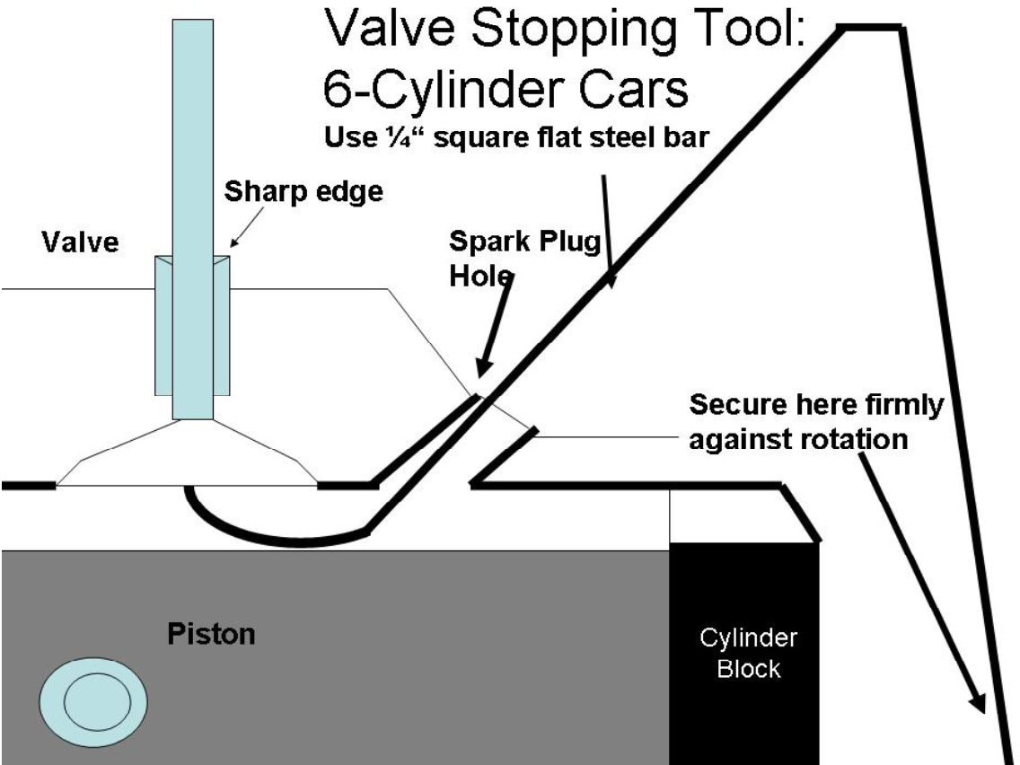
Figure 4
Silver Spirit extract on RTV application
Prior to fitting the collets and top washer, ensure that they are degreased and the valve tip area around the collet locating groove is wiped clean. Arrange the collets inn pairs on a clean surface and apply Silastic 732 RTV sealant along one edge of one collet abuts the uncoated edge of the other.
Allow 10 minutes to elapse before assembly. Keep the gaps between the collets equal and wipe any excessive sealant from the valve tip and top washer.
Allow a further period of at least twelve hours to elapse from applying the sealant to running the engine.
Valve Stem Seals – Caution upon Installation
The replacement valve stem seals provided for your engine rebuild by Introcar are of the highest quality. They are of the positive type, made from Viton® with a metal casing. They offer ideal oil control, minimising oil loss and keeping the valve stems and valve guides optimally lubricated at all times. Through their superior behaviour, they will reduce oil consumption significantly, whilst greatly reducing valve stem and valve guide wear. This in turn prolongs the life of the valve seats and faces markedly.
The seals are not unlike those adopted by Crewe from the mid-1980s onwards, but through the use of the best materials and detail design, the Introcar seals provide a useful improvement in durability and precision.
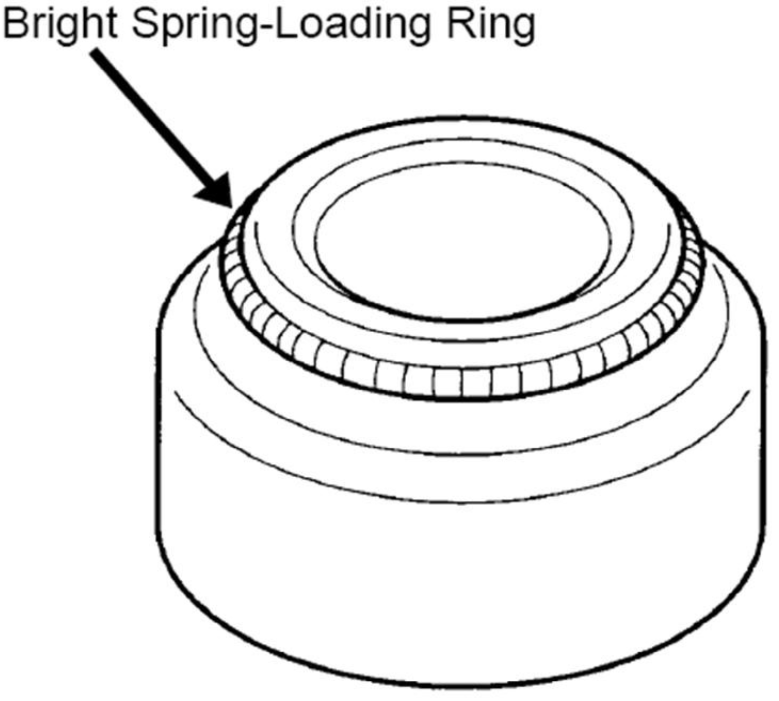
An important feature of the seal is its bright spring-loading ring around the Viton® sealing neck.
Please ensure that the spring ring is positioned correctly in its groove around the seal neck.
It is unlikely but possible that the spring ring be disturbed or dislodged during handling or shipping. In some cases, it is even possible that, on opening the package, the spring ring is separated from the seal and may be found loose in the packaging.
If it has been dislodged or disturbed, simply roll the spring ring over the seal’s neck and neatly into its groove.