Valve Lifter & Hydraulic Tappet Push Road Pre Load Measurement Information
Valve Lifter & Push Rod Pre Load Testing
One problem that has increased in frequency in recent years is noise from the engine tappet chest. Through our research with the Rolls-Royce and Bentley Specialist’s Association, it has become clear that problems are associated increasingly with incorrect pre-load on the push rod and hydraulic valve lifters.
As the V8 engine has become older repairs and overhaul have become common, and in many cases an engine that is being worked on may already have been subject to overhaul on one or more occasions. In particular, cylinder heads may have been re-faced at least once, effectively reducing the distance between the rocker and camshaft. This may be sufficient to take movement of the internal valve in the hydraulic valve lifter outside its acceptable range, which causes noise in one or (more often) several hydraulic valve lifters.
Several factors can affect push rod/valve lifter pre-load:
1) Re-facing of the cylinder head and crankcase mating faces
2) Wear on inlet and exhaust rockers
3) Wear in valve valves and valve seats or incorrect “lapping in”
4) Worn camshaft, incorrect engine oil, low oil pressure or seized valves
The following instructions will allow you to ascertain how much pre-load there is on the push rods in your engine.
You will need the following items:
1) 3/8” large washer
2) Vernier scale (or caliper)
3) White paint pen
4) Scribe
5) Rocker tool UE8767TOOL to measure pre-load
Procedure
Familiarise yourself with the workshop manual in relation to the replacement of hydraulic valve lifters and associated operations. A copy of this information is available free from IntroCar.
Pre-Checks
1) Flush the engine to remove debris, fit a new oil filter and fill with engine oil of the correct specification
2) Run the engine for 30 minutes to ensure the pump and filter are primed
3) Remove the tappet chest, rocker covers, rocker shafts, push rods, valve lifters and tappet blocks, following procedures outlined in the workshop manual
4) Check that the replacement tappets slide easily in the tappet blocks. A tappet should fall through the tappet block under its own weight. If necessary, ridges in the blocks may be removed with a light hone
5) Examine the camshaft for visual signs of wear. Important: the camshaft must turn the valve lifter as it rotates. This is achieved via a minute but precise taper in the camshaft lobe and a slightly convex face on the bottom of the valve lifter The interaction between the taper on the lobe and the curve on the face of the valve lifter is sufficient to rotate the lifter in use. It may not be able to detect wear in the camshaft without precise measurement using the correct instruments. Camshafts and hydraulic valve lifters tend to “bed in” together over years of operation. A used camshaft, therefore, may not work with new lifters. If in doubt replace both camshaft and lifters. When assembled, you must check that all the lifters are being turned by the camshaft. If the lifters are not turning engine failure normally occurs within a few hundred miles.
Assembly & Checking of Preload
-
Re-fit tappet blocks making sure to replace the locktabs (XB7106R)
-
For the first valve lifter you wish to check, turn the engine so that the relevant camshaft lobe is at bottom dead centre
-
Fit the valve lifter to the tappet block. The lifter should be fitted “dry”. It will prime and self-adjust through the operation of the engine
-
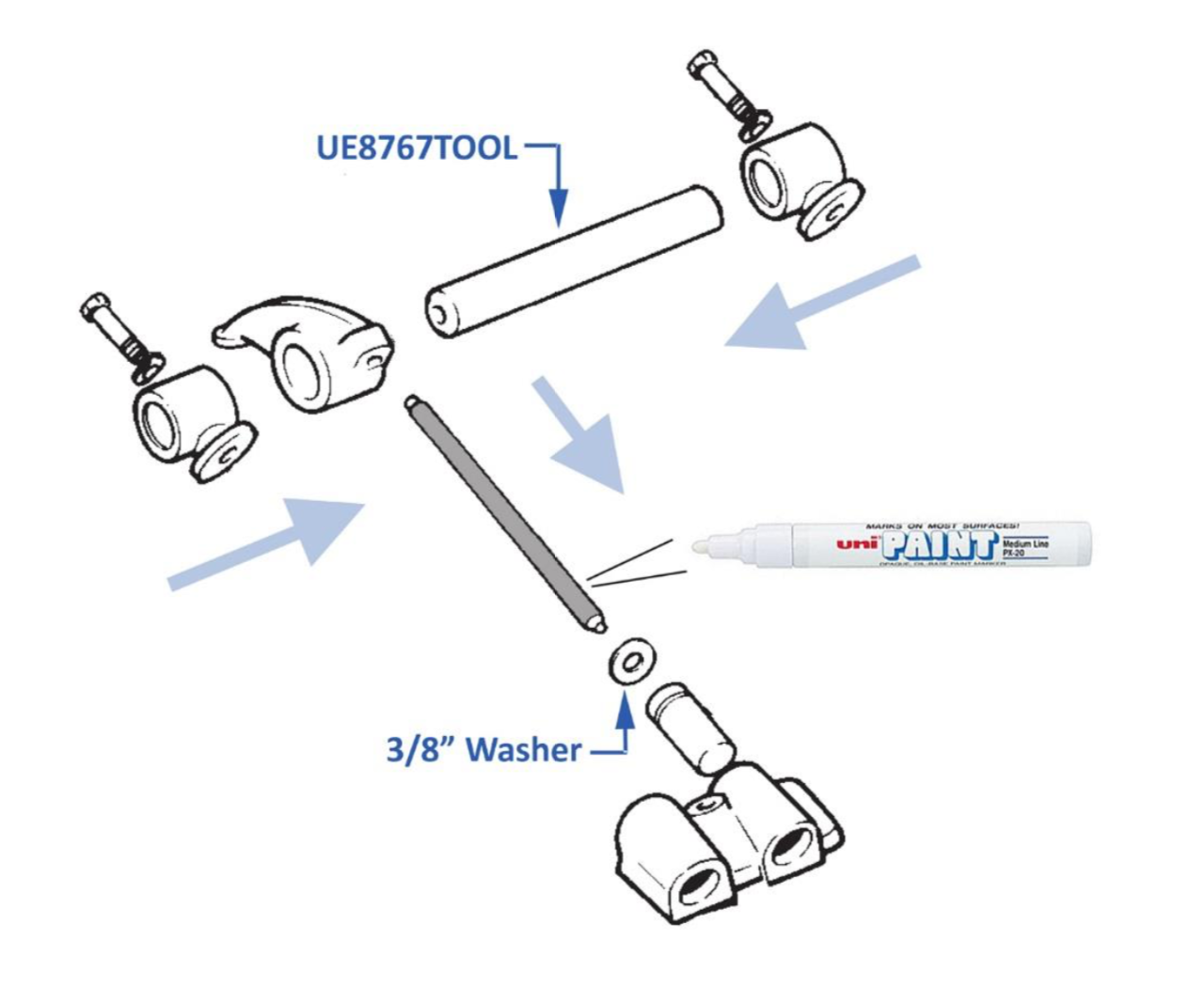
Fit the 3/8” washer over the top of the lifter and slide in the push rod until it is seated in the valve lifter
-
Fit UE8767TOOL into the rocker pedestals either side of the lifter you are working on. Tighten the pedestal screws so that the pedestal bases on both sides are just touching the cylinder head – only enough that the base and head are in contact
-
Mark the push rod with the white paint pen where the top of the washer and the push rod align. Make the marking wide enough so that you can scribe two lines in the white paint (say 6-8mm or 1/4-3/8”).
-
Tighten the rocker pedestal screws down to the correct setting (8-10 lb/ft or 1.1-1.4 kg/m)
-
Scribe a first line in the white paint, where the top of the washer aligns with the push rod.
-
Release the tension on the tool by unscrewing the rocker pedestal screws
-
Scribe a second mark in the white paint in line with the top of the washer.
-
Remove and repeat for the remaining 15 push rods and valve lifters
-
Measure and record the gaps between the two lines on each of the 16 push rods using the Vernier scale
Interpretation of Results
If the gap between the two lines is 4 mm (0.157”) or more then valve lifter pre-load is excessive. This is likely to result in noise from the valve lifters when the engine is assembled.
I have excessive Pre-Load. What do I do now?
First, check the valves, valve seats and rockers, as per the workshop manual. If these are in good condition, it is likely that the cylinder head and/or crankshaft faces have been machined sufficiently to decrease the distance between rockers and camshaft, causing excessive pre-load on the hydraulic lifters.
In order to resolve this issue, shorter engine push rods have been developed, the purpose of which is to alleviate excessive pre-load.
For Rolls-Royce Silver Cloud II, Silver Cloud III, Phantom V & Phantom VI (prior to chassis number PRH4108), and Bentley S2 & S3, order RH14157-0.050-X.
For Silver Shadow, T1, Corniche, all SZ series cars, and V8 Red Label Arnage (Not Silver Seraph, Green Label Arnage or Arnage T), order UT14120PA-0.050-X.
If you have any queries, please do not hesitate to contact us.