Fitting Instructions - Suction Throttle Valve CD6687
Fitting Instructions - Suction Throttle Valve Kit CD6687-X
CD6687 is an electronic modification kit to replace the original suction throttling valve UD11429. It works by blanking the original valve (which is left in situ) and replacing it with an electronic switching unit.
Below are instructions to accompany the fitting of part number CD6687-X.
1. Evacuate & recycle existing refrigerant from system
2. Removal of the STV valve from the vehicle is recommended
3. Loosen outer diaphragm locking nut on housing
4. Carefully unscrew outer diaphragm from housing. Caution: Spring under tension
5. Remove screws from outer diaphragm housing & separate valve halves
6. Discard spring, inner diaphragm & piston
7. Insert Gasket & Reinforcement plate as shown
8. Screw outer diaphragm locking nut towards base leaving approximately 1/8 inch of threads visible (this will let plunger clear update plate)
9. Using valve core tool, remove valve core from (male insert o-ring) oil bleed line fitting only. Caution: Do not remove valve core from the male flare charging port
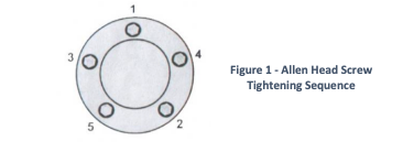
10.Reverse steps 5 through 3 to reassemble valve, using the new allen head screws supplied.
11.Reinstall valve on vehicle & complete wiring modification (next steps)
12. For vacuum operated valve insert vacuum restrictor (ball bearing) into vacuum line leading to valve (disregard this step for Cable or motor operated STV valves).
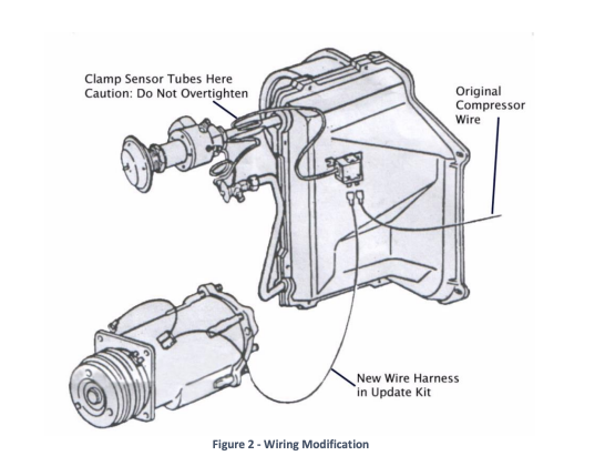
13. Using Clamp, secure thermostat sensor tube onto suction outlet tube of the evaporator near the temperature sensing bulb of the expansion valve. Surface must be clean for good contact.
14. Wrap thermostat sensor tube at evaporator outlet with insulation tape provided.
15. Mount thermostat to evaporator case using screws provided. Be sure not to puncture evaporator core.
16. Connect original compressor clutch wire to the thermostat using electrical connector provided.
17. Connect the new clutch wire provided from the remaining terminal on thermostat to the compressor clutch coil.
18. Have system evacuated & recharged by a qualified A/C technician.