IntroCar managing director John Tupper explains how replacement parts are made by measuring the originals when engineering drawings are not available
MANY CLUB MEMBERS will know what a valuable resource The Hunt House archives are. For us parts manufacturers they are particularly useful because they contain engineering drawings for many components that are no longer available from the factory but which the industry continues to need. The reason this is important is that engineering drawings contain critical information relating to the types of materials used, the measurement tolerances on components and subcomponents, and the correct finish. Get these wrong and the part might not fit properly or even fail. But what happens when a drawing is not available? At the Rolls-Royce and Bentley Specialists Association (RRBSA), we’ve worked hard to devise a standard that enables our members to reverse engineer parts to match the original component. This article gives a brief insight into what this means in practice.
STAGE ONE: CREATE A DRAWING
If you have no original engineering drawing, then it’s important that you create your own. A drawing provides a defined specification against which a product can be assessed. Creating a drawing will mean measuring or 3D scanning an original product (or better, several examples of the product) to establish the basic dimensional specifications. These will need to be confirmed and tolerances added. Material specifications and tolerances may be replicated from other similar components where original specifications are available. Use of a laboratory to analyse materials, or consulting with specialist third party engineers, can help confirm the materials you propose to use. Creation of, or conversion to, a drawing in autoCAD (software that replicates the part in 3D) is useful both for programming machines used for manufacture and for quality audits during the latter parts of the process. It is worth pointing out that drawings created in this way may be subject to revision many times until an appropriate final specification is determined.
Engineering drawings contain critical information on materials, tolerances and finish. Get these wrong and the part might fail.
STAGE TWO: SAMPLES FOR ASSESSMENT
Once you have a defined specification, the next step is to ensure the manufacturer can create a product that is within that specification. Almost always this means asking the manufacturer to produce prototypes in a small quantity which can be measured, tested in the laboratory, and fitted to test vehicles. Manufacturers are asked to produce certificates that demonstrate that the materials employed are correct and any treatments or processes applied are as described on the drawing. Samples may be measured using calibrated measuring tools or, in the case of complex parts, a CMM (Component Measuring Machine) may be used.
CMMs use extremely accurate probes to compare the individual product being measured alongside the measurements on the drawing. In this case a 3D autoCAD drawing demonstrates its efficacy, as it can be programmed into the CMM. The CMM produces a report, highlighting any measurements that are outside the relevant specification. Once programmed, the CMM can repeat this operation as many times as is required, faster and more accurately than a human could do. More particularly, if the samples are off-specification, you need to know exactly where and by how much so that the manufacturer can alter its process accordingly. If the sample is within specification, then a fit-test will determine whether the drawing itself needs revision, which would require providing a new version of the drawing and the production of further samples.
It should be remembered that, with complex components, each subcomponent must be assessed the same way, alongside the assembly itself.
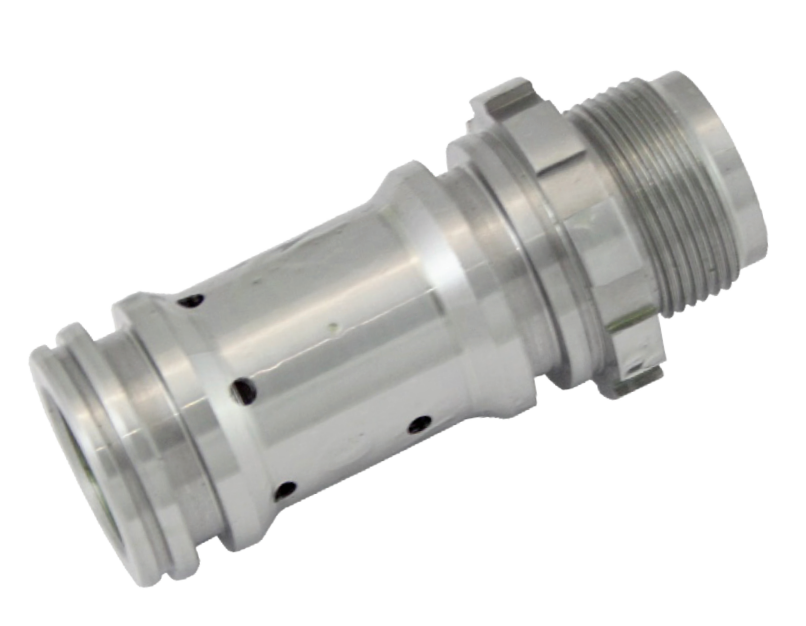
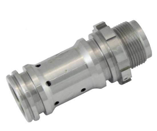
Pre-inspection of this reverse engineered brake pump housing involved 10% of the production batch being subject to more than 100 measurements by CMM to ensure they were within accepted tolerances
STAGE THREE: PRODUCTION
Once samples and the original drawing have been approved, the manufacturer can move to production. It is normal to ask the manufacturer to inspect product before supply (usually completing an inspection pack, or form, which demonstrates that the manufacturer knows which areas are critical and ensuring that product is not supplied manifestly off-specification). Depending on the product, 100% inspection may be undertaken, or just a sample taken from the batch. In the case of complex products, manufacturers often employ their own CMM to audit goods before despatch. For example, before the brake pump housing (above) was supplied, 10% of the production batch underwent more than 100 measurements per component on the manufacturer’s CMM, all included in the pre-supply inspection report. Once pre-supply inspection has been approved, the goods may be delivered and then quarantined for an in-house inspection. During this time, laboratory testing is performed on a small subsection of the stock. Of course, this is a vastly simplified account, which more technically-minded readers will realise does not apply to all products. However, the RRBSA hopes it provides some idea of what is involved on those rare occasions when the inestimable archives at The Hunt House are found wanting.
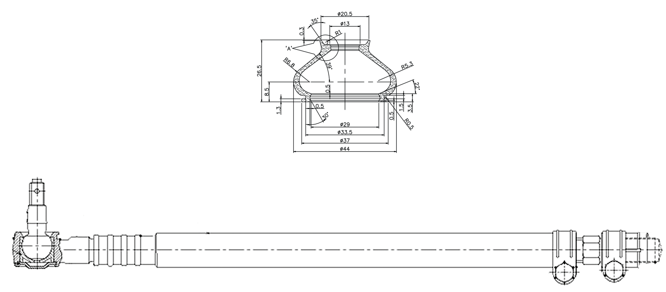
An extract from the assembly of a steering track rod, currently in production
WHAT IS A CMM?
A coordinate measuring machine (CMM) such as Aberlink’s Axiom Too (illustrated) accurately measures the geometry of an object along the X, Y and Z axes by using a touch-trigger, scanning or vision probe to record a series of precise points on the surface of an object. The most common use of a CMM is to test the accuracy of a manufactured part against its original design. CMMs are generally made from a combination of granite and aluminium due to its stiffness-to-weight ratio while allowing the constructed materials to be thermally dynamic. Changes in ambient temperatures and thus expansion or contraction of the CMM’s materials are compensated for by the software.
TECHNICAL INSIGHT : parts production, RREC's Spirit & Speed March 2020
With thanks to Spirit & Speed : Issue 359
Article Published March 2020 rrec.org.uk
